I. OVERVIEW OF THE BUSWAY GUIDE SYSTEM
Symbols and details to know:
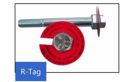
| The articulated tightening bolt is specially crafted, has 2 caps, and in the middle is a red guide stamp. When the upper cap is tightened enough, it will break and the stamp will fall out. Tightening force breaks approx
> 800kgf.cm |
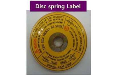
Bellevile discs maintain the tightening force of the bulon for a long time. Avoid self-loosening of the bulon due to thermal expansion.
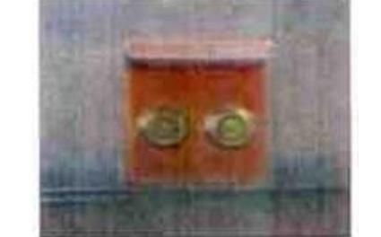
| Pole used to connect to wires or grounding systems of other equipment. Mounted at the cabinet connector, cable connector...and in the Plug-in unit box. |
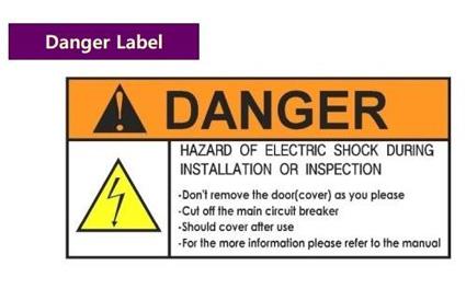
Danger warning stamp
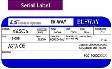
Stamps represent detailed Busway parameters: Configuration, material, voltage, rated current, IP, production date, guide bar order symbols on the drawing.
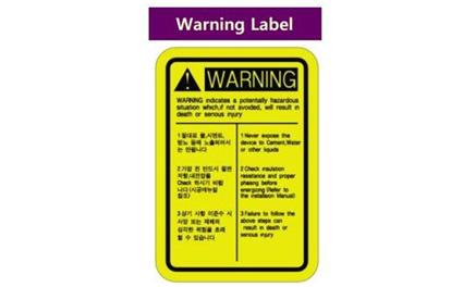
Stamps warn of agents that may affect or damage the Busway such as water and cement... Recommended inspection operations before closing power
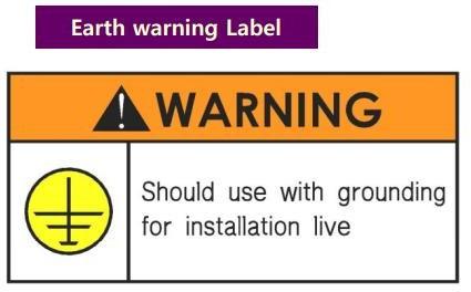
The stamp indicates the ground position of the Plug in unit box
BUSWAY SYSTEM MAINTENANCE
Busway systems are widely used and are an indispensable component in the electrical systems of factories, apartment buildings, and hotels... Like many other industrial electrical systems, Busway systems also need to be operated. correct technique and periodic maintenance according to the correct process.
PROBLEMS WITH BUSWAY INSTALLATIONS
Globally, guide bar problems occur with almost all firms at specific constructions. In general, the incidents are summarized by firms as follows:
– Due to manufacturing: almost rare, because all factories test (insulated with Mega Ohm meter – (must reach infinity value) and discharge with voltage of 3000VDC each product before shipment. Except in cases of impact during transportation, mechanical impact (twisting, ),... Therefore, inspection before and after installation is required to remove failed products.
– Due to the connector not tightening: leading to discharge and damage. To fix it, global brands have connectors that tighten with a 2-headed boloon. When tightening, you only need to tighten one end until the upper screw splashes out to have enough tightness (800-1000kgN/cm2)
– Due to water seepage: Almost all brands with IP 54 when a long-term water seepage situation occurs will lead to problems with the guide system. Therefore, a dry storage environment and guide bar installation location are required.
– Because all heavy loads start at the same time: Very rarely, but there have been cases in the world.
– Due to a strange conductor shortening the circuit of the conductors at the connection location: this is an installation error and all companies must also give up when this happens.
– Due to suspension damage: Leads to tilting, twisting, twisting, and very rarely occurs.
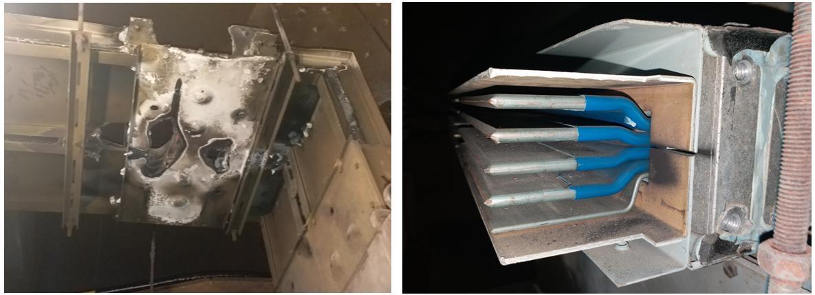
– Due to the poor clamping mechanism between the power box and the guide bar, it leads to a fire and explosion at the PH Box power box location (Very common, mainly at some Busway companies with poor
II. BUSWAY MAINTENANCE WORK DETAILS:
1. MEASURES FOR SURVEYING AND EVALUATING BUSWAY SYSTEMS
| No. | Description |
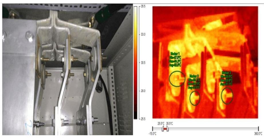
| 1 | Take thermal images of the busway system and all joints (scan the entire location, but only print reports of typical locations and hot locations that pose a risk of causing problems during operation). |
| 2 | Overview of deterioration and discoloration of insulation and contact surfaces. |
| 3 | Check for corrosion, abrasion, dirt or signs of discharge. |
| 4 | Check to detect damaged and abnormal details (if any). |
| 5 | Check for moisture, water leaks from the ceiling or pipes above the busway (if any). |
| 6 | Check and tighten all mechanical bolts, suspension companies, and load-bearing racks throughout the system using specialized equipment. |
| 7 | Industrial cleaning of the entire busway system. |
| 8 | Insulation resistance test for busway system with standards as follows: >100MΩ with system length from 0 to 15m >50MΩ with system length from 15 to 60m, >20MΩ with system length over 60m. |
| 9 | Prepare comprehensive reports before and after maintenance including: + Volume up the work done during maintenance. + Propose detected existences on the system and solutions to handle detected existences. + Quote for replacement materials and repair plans with discovered shortcomings. + Advise on materials and equipment that may need repair or replacement within the next 1 year. |
2. BUSWAY SYSTEM MAINTENANCE MEASURES :
Determine the operating time and length of the Busway system to come up with an appropriate maintenance plan
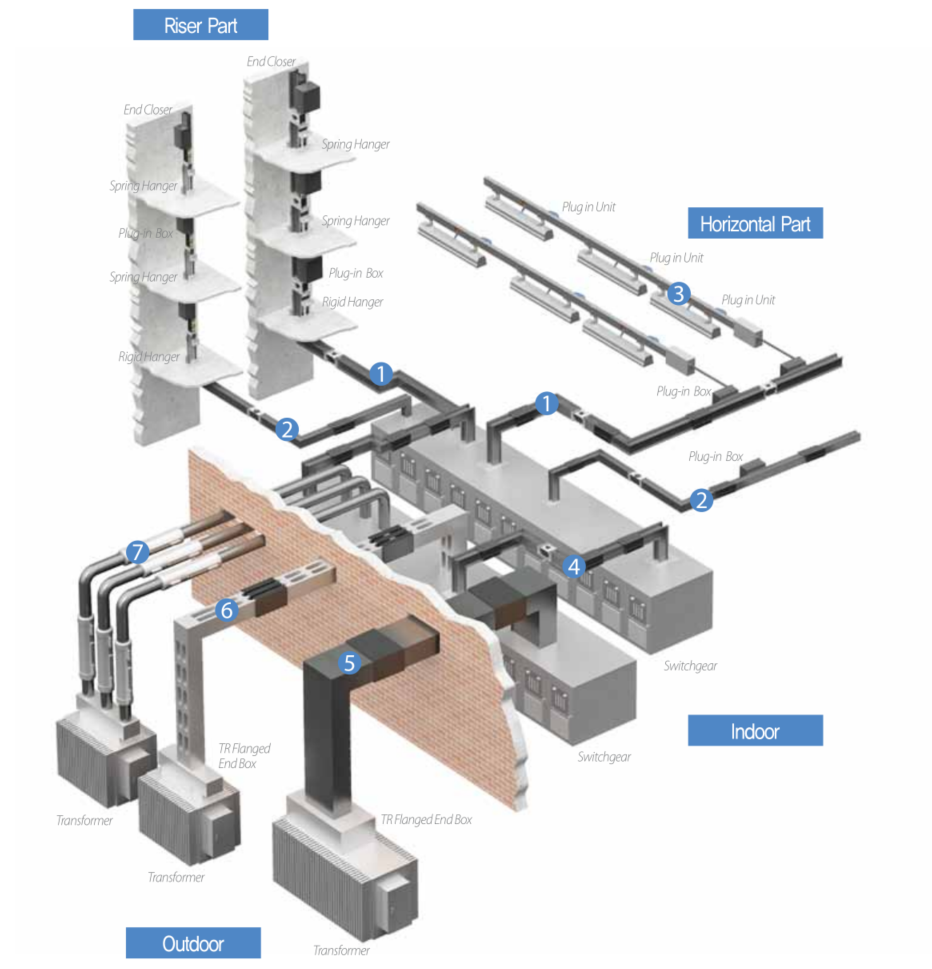
- Inspect, vacuum and sanitize the entire vertical and horizontal axis busway, diversion joints, electrical cabinet connectors, generators and transformers…
- Inspect the entire suspension arm, horizontal and fixed bracket, spring bracket for the vertical shaft, recalibrate the warped brackets…
- Check, clean and tighten the screws connecting the Busway with electrical cabinets, generators and transformers.
- Perform temperature checks (thermal scans) of Busway guides and especially at joints and plug-in box cabinets in the state that the Busway is carrying the load.
- Use a specialized temperature meter to periodically check Busway's working temperature every 01~02 months. The temperature increase of the busway allows it not to exceed 55 degrees Celsius above the ambient temperature when operating at full load.
- Analyze thermal scan results to come up with a specific maintenance plan for each location.
III. HANDLING MEASURES IN CASE OF PROBLEMS:
1. When we detect that the Busway has a problem causing the protection device to jump (ACB, MCCB), we follow these steps:
– Determine the cause and location of the problem (listen to sounds, sirens,...)
– Isolate all Busway-related equipment (Transformers, Generators, Auxiliary electrical cabinets, floor electrical cabinets,...)
– Use a megahom meter to check the insulation of the entire system (Test the insulation between phase-phase, phase-neutral, phase-Busway shell, neutral-Busway shell) with Megaohm Tester with a scale of 1000 VDC). If the measurement parameters are satisfactory. (>20 Megaohm) then proceed to turn off power to the entire system.
– If the insulation measurement is not met, there is a high possibility that the system will shorten or absorb water, so you must notify the supplier for timely treatment measures.
2. Handle when the cutter is OFF due to a short fire in the PH Box and power opening.
Conduct axial inspection of the busway at the power collection boxes at all disassembled floors to check and comprehensively evaluate the power collection points. Determine how many openings and which PH Box power is being used to handle. Make a treatment plan with the Project Management Board and schedule a power cut with the Building Management Board.
Plan to repair and replace each or all of the points affected by the fire.
After completing the installation, the PH Box box system has been repaired back to the Busway system, check the insulation of the entire system (Test the insulation between phase-phase, neutral phase, phase- Busway shell, neutral-Busway shell) by Megaohm Tester with 1000 VDC scale).
Busway system installation inspection is only completed when the above Test parameters meet the requirements.
20 Megaohm).
Conduct power closure for the entire system, monitor stability within 24 hours.
3. Handle errors when a short circuit burns, explodes the Joint Kit or explodes the guide bar
Judging the cause of the short circuit phenomenon: Because the installed busway system has a poor contact surface or water seeps into the joint, it leads to heat generation, damaging the insulation layer, causing touch and short circuit, leading to arc discharge. Heat generation causes fire, damaging the insulation layers, so the phases will short circuit, and launch back into the transformer and crack the insulation layers throughout the length of the guide bar.
Solution:
- Dismantle the entire troubled part from the system, support the use of a temporary connection troubleshooter to close the power to ensure the maintenance of the system's power source.
- Conduct an assessment of damaged parts that need to be ordered with the carrier for replacement
- After the goods arrive, cut off the power, remove the troubleshooter and completely reinstall the system
- Conduct measurements, check system calibration and return power to the system.
4. Handle errors due to water seepage into the system and jumping MCCB, ACB or short circuit breakdown.
– Inspect the entire system, measuring megaom and segments to separate the water-soaked Busway part from the system.
– There is a way to connect a temporary power source to the system.
– Remove each water-soaked Busway bar from the system, take it to the factory for disassembly and water infiltration treatment, and re-wrap the insulation layer of the heavily soaked bars.
– After re-measuring the insulation of each bar, ensuring the insulation parameters, the repaired Busway bars will be reinstalled into the system. Measure and re-insulate the entire system. If you ensure the insulation, it will be restored. Re-power the Busway.

